|
Insert
Commands for inserting new entities.
Creates a line that passes through two given points.
Creates a broken line (sequence of consecutive lines). The broken line itself is not a single entity, the lines it is formed by are single entities; as such they can be used and modified.
Creates a parallel line to a selected existing line that passes through the given point.
Creates a new line that is inclined to the selected (existing) line by an angle and that starts from the entered point (its first vertex).
Creates an arc that passes through three points. The first and last point input define the initial and the final vertex of the arc; the second point input determines the arc defining a common point on the arc. The three points cannot be aligned.
Creates a circle with center at the first point and passing through the second.
Creates a circle that passes through 3 given points. The three points cannot be aligned.
Opens a window in which it is possible to enter a text without limitations in size, and which can be disposed on one or more lines. Then asks you to select the point where to insert the text.
Creates an entity of the point type.
Creates a rectangle whose diagonal has the two selected point as vertices. A rectangle is formed by a single polyline which consists of several lines.
Generates a polyline composed of linear stretches that connect the input points. The End Selection command, available from the context menu, finishes the insertion of the points forming the entity.
Creates a spline as interpolation of the inserted points. The End Selection command, available from the context menu, finishes the insertion of the points forming the entity. The maximum of points for the construction of a spline is 100.
Lets you execute the hatching of a closed perimeter requiring the input of only one side of the perimeter. Selectable entities are lines, circles, arcs and ellipses. The command doesn’t consider eventual perimeters inside the selected perimeter. The perimeter can be formed by a maximum of 5000 entities. If the selected entity belongs to only one closed perimeter is uninfluential the position of the center of the trap selection.
Creates a hatching of a closed perimeter by the selection of one entity that belongs to it excluding the “lakes”, i.e. the closed perimeters inside the perimeter. Selectable entities are lines, circles, arcs and conics.
Creates a dimension that measures the distance between the two points positioning it in the third point inserted.
Creates a dimension that measures the angle formed by two lines positioning it in the third point inserted.
Creates a dimension that measures the diameter of the circle (or of arc) is selected positioning it in the point inserted.
Creates a dimension that measures the radius of the circle (or of arc) is selected positioning it in the point inserted.
More about dimensions
The position of the dimension text depends on the Optimum dimensioning setting: if active the dimension is automatically centered, otherwise it is positioned at the inserted point. The Optimum dimensioning can be set in the General page of the CAD Options window.
The dimensions are associative, that is memorize which are the entities that measure. This associativeness enables the dimension to immediately adapt itself to a new geometric situation that may be caused by the transformation or the modification of an entity. You can delete this associativity with context command Detach.
Dimensions except for angle dimensions can be supplemented by tolerances. Tolerances indicate the maximum margin that the measured dimension is allowed to have with regard to the nominal dimension. Tolerances can be set in Dimensions page of Attributes window. You can set tolerances as well by inserting their ISO code. In this case the values of the upper and lower tolerances are calculated automatically by the program that bases its calculation on the ISO code and the size of the dimension.
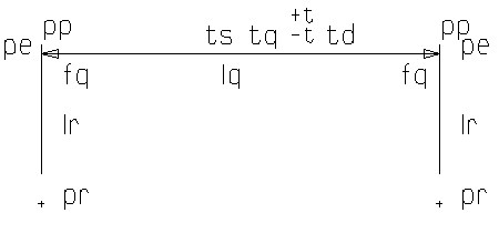
The following schema illustrates a typical dimension:
abbr. description: fq arrow lq dimension line lr reference line pe extension point pp projection point pr reference point t+ upper tolerance t- lower tolerance td text on the right tq dimension text ts text on the left
|
